


Date:2018-3-19 Hits:5011
GE ATS-M-3
ATS Achilles Test Software Maintenance - 3 years
Zenith ZTG Series
Low-Voltage Automatic Transfer Switches
GE’s Zenith ZTG Series switches are built for
standard applications requiring the dependability
and ease of operation found in a power
contactor switch.
• Ratings 40 to 3000 amps (2, 3 or 4 poles)
• UL 1008 listed at 480 VAC
• CSA certified at 600 VAC
(200-260 amps - 480V)
• NFPA 70, 99, 101 and 110
• IEEE 446 and 241
• NEC 517, 700, 701 and 702
• NEMA ICS2-447
• UL 508 and 50
• ANSI C33.76
• ICS 6
• NEMA 250
• Equipment (Controls and Power Section)
Seismic Test Qualified to:
IBC-2006
IEEE-693-2005
• Double throw, mechanically
interlocked contactor mechanism
• Electrically operated, mechanically held
• Designed for emergency and
standby applications
• Available in standard (ZTG) or
delayed transition (ZTGD) models
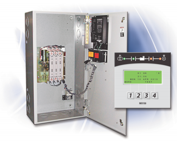
ZTG switches are equipped with GE’s Zenith
MX150 microprocessor panel, which controls
the operation and displays the status of the
transfer switch’s position, timers and available
sources. As an embedded digital controller,
the MX150 offers high reliability and ease of
unattended operation across a range of
applications. The MX150 features include:
• Timer and voltage/frequency settings
adjustable without disconnection from
the power section
• Built-in diagnostics with an LCD display
for immediate troubleshooting
• LED/LCD indicators for ease of viewing
and long life
• Nonvolatile memory—clock battery backup
not required for standard switch operation
• Processor and digital circuitry isolated
from line voltage
• Inputs optoisolated for high electrical
immunity to transients and noise
• Communications network interface
Fully Approved
• UL and CSA listed
• NFPA 70, 99 101 and 110
• IEEE 446 and 241
• NEC 517, 700, 701 and 702
• NEMA ICS2-447
• UL 508 and 50
• ANSI C33.76
• ICS 6
• NEMA 250
• IBC-2006
• IEEE-693-2005
• Ringing wave immunity per
IEEE 472 (ANSI C37.90A)
• Conducted and Radiated Emissions per
EN55022 Class B (CISPR 22) (Exceeds
EN55011 & MILSTD 461 Class 3)
• ESD immunity test per EN61000-4-2
Class B (Level 4)
• Radiated RF, electromagnetic field
immunity test per EN61000-4-3
(ENV50140) 10v/m
• Electrical fast transient/burst immunity
test per EN61000-4-4
• Surge immunity test per EN61000-4-5
IEEE C62.41 (1.2 X 50μs, 0.5 & 4 kV)
• Conducted immunity test per
EN61000-4-6 (ENV50141)
• Voltage dips and interruption immunity
EN61000-4-11
Design and Construction Features
• Close differential 3 phase under-voltage
sensing of Source 1 (normal)—factory
standard setting 90% pickup, 80%
dropout (adjustable); under-frequency
sensing of Source 1 factory setting
95% pickup (adjustable)
• Voltage and frequency sensing of the
Source 2 (emergency)—factory standard
setting 90% pickup voltage, 95% pickup
frequency (adjustable)
• Test switch (fast test/load/no load) to
simulate Source 1 (normal) failure—
automatically bypassed should the
Source 2 (emergency) fail
• NEMA Type 1 enclosure is standard—
also available in open style or NEMA
Types 3R, 4, 4X or 12
Standard Features (MSTDG Option Pkg.)
Front View
6/P Test Switch, Momentary
A3 Auxiliary Contact: Closed when the switch is in the Source 2 position (S2)
A4 Auxiliary Contact: Closed when the switch is in the Source 1 position (S1)
CALIBRATE Capabilities are available for Frequency and AB, BC, CA Phase to Phase
voltage for both Sources
CDT Daily 7, 14, 28 timed exercise (CDT memory backup battery included),
pushbutton/timer operation
E Engine Start Contact
EL/P Event Log of 16 Events that track date, time, reason and action taken
J1E Adjustable under frequency sensor for S2
K/P Voltage and Frequency Indication for S1 and S2
L Indicating LED Pilot Lights:
L1 Indicates switch in S2 position
L2 Indicates switch in S1 position
L3 Indicates S1 source available
L4 Indicates S2 source available
P1 Time Delay to Engine Start
Q2 Peak Shave / Remote Load Test
R50 In-Phase Monitor, self-adjusting
T Time Delay on Retransfer to Normal: To delay retransfer to S1
(immediate retransfer on S2 failure)
R2E Under voltage sensing of S2
S13 Microprocessor activated commit / no commit on tranferring to S2
U Time Delay for Engine Cool Down: Allows engine to run unloaded after
switch retransfer to S1
W Time Delay on Transfer to Emergency: To delay transfer to S2 after availability
YEN Pushbutton Bypass of T & W Timers
When specified for use with a ZTGD Series delayed transition switch, the control panel
also includes the following:
DT Time Delay from Neutral Switch Position to S1 on Retransfer
DW Time Delay from Neutral Switch Position to S2
LN/P Center-Off position/Off Delay Timing indicating lights
MX150
S 1 OK * E *
21: 56
MON 1 0 AP R 2 0 1 0
MORE T E S T
Additional Standard Features (MEXEG Option Pkg.)
CDP Clock Exerciser Load/No Load (Replaces CDT Exerciser Option)
VI Voltage Imbalance Monitor (Three Phase)
Switch Types
• Standard: Unless otherwise noted, the
standard switch with quick transfer will
be supplied.
• Delayed Transition: When ordered as
the ZTGD, the delayed transition switch
offers time delay during transfer from
one position to the other. This is primarily
for transfer of large motor or inductive
loads. The operation of the delayed
transition switch is totally independent
of the synchronism of the power sources,
eliminating the need for in-phase monitors
or extensive motor-disconnect control
wiring between the transfe
Example
ZTG000A00040F-ZEC01ZVC40MSTD
This number string shows the correct format
for a ZTG Series Automatic Transfer Switch
with an MX150 microprocessor control unit,
Utility - Generator, 400 amps, 4 pole, NEMA
Type 1 enclosure, 120/208V 3φ, 4 wire, 60 Hz
system with the standard group of accessories.
 Salesman-1